Walls have ears but could they
have mouths as well? An alternative to thermo-elastic model of microwave
hearing allows for human hearing of a.m and f.m as well as pulse signals. By Dr Chris Barnes, Bangor Scientific and Educational Consultants,
Bangor, Gwynedd, Wales, UK e-mail manager@bsec-wales.co.uk
REVISED AND RE-PUBLISHED NOVEMBER 2015
Abstract
A new
hypothesis is developed to account for why buildings are required in some
people’s perception of the acoustic phenomena known as the ‘Hum’. Causes of the Hum are usually put down to
Acoustic or radio – frequency phenomena.
In the case of the latter the field strength of pulsed signals in the
offending buildings is rarely, if ever, large enough to account for Hum
perception by thermo-elastic means. Low
frequency electromagnetic energy may however be directly converted to acoustic
energy by rectification and a piezoelectric transducer effect in outer building
walls.
Introduction
This present paper attempts to explain how some
people might perceive the phenomenon known as the Hum, which is often only
heard by those afflicted at night and inside buildings. Some cases of the Hum have been explained in
terms of infrasound of external original and/or low frequency noise
(refs). Others account for the Hum in
terms of the so –called microwave hearing effect (refs) the only proven
mechanism of which is the so-called thermo-elastic model.
However, there are many cases of the ‘Hum’, which
as yet remain totally unexplained.
These are cases wherein there is no externally measurable sound field
and no externally measurable seismic vibration.
Those advocates
of a Hum of electromagnetic origin would in these cases
advocate electromagnetic signals for its causality. (Refs)
The only known proven mechanism by which humans are
known to detect and ‘hear’ electromagnetic signals is microwave hearing by the
so-called so-called thermo-elastic model. (refs). However, in order to hear such signals they have to
be both pulsed and above a certain threshold radio frequency field
strength. (refs).
Such pulsed microwave signals are often perceived by humans as a such pulsed microwave signals are often perceived by
humans as series of clicks (ref) which is uncharacteristic of what people
subjectively describe as the Hum.
Further, indeed, and as result of NRPB limitations, it is rarely if ever the case that field
strength of pulsed signals in the offending buildings is ever, large enough to
account for Hum perception by thermo-elastic means. Such pulsed signals might
be expected to arise from GSM and CDMA mobile phone installations, airport
radar systems and DAB and DVB broadcasting.
That is not to say other mechanisms for electromagnetic hearing have not
been proposed. There are several including; quantum biological models (ref)
direct interaction with the cochlea or acoustic nerve (refs) and bioactive ferritin
in the brain (ref). However, as far as the author is aware none are as yet
tested and proved.
So what of an entirely new mechanism? What if the conversion of electromagnetic
signal to sound / infrasound takes place external to the body but within the
very fabric of the house itself!
Hypothesis;
Cavity wall as a radio receiver.
Most UK
houses since as early as 1932 use so-called ‘cavity wall’ construction.
Essentially the outer load bearing walls of the house feature a double brick
skin separated by a layer of air and locked together at regular intervals by so
called ties or tie bars. Early ties were flat slightly twisted steel bars
and corroded readily. Even more modern
ties, which are bow tie shaped pieces of galvanised steel wire, will corrode in
places where the galvanisation is compromised. In any case in the galvanised
system there are two dissimilar metals, the ideal scenario for a rectifying
junction. In the early system the rust /steel interface could act as a
rectifying junction. Many ceramics of
which brick is an example are semi-conductors, another possibility for radio
demodulation. The ‘rust nail’ effect is
well documented amongst radio engineers ( refs) and
thus it is at least possible to see how a house cavity wall might demodulate a
radio transmission. Such rectifier demodulation will work for AM transmission
(envelope demodulation) or FM (slope demodulation).
However
in any radio receiver transmission we need an output transducer. These days there would be several stages of
amplification driving a moving coil loudspeaker. In the early days of radio a crystal detector
would energise headphones directly the dc bias being extracted from the rf carrier wave.
So what
of the output transducer system in our cavity wall? Brick and cement mortar is a naturally
piezoelectric material. So here we have
it. The demodulated signal from the brick/tie bar system directly energies the
brick, which will then vibrate mechanically in sympathy with the driving
waveform. It would be expected that such
vibrations would be of minimal amplitude and hence only perceived at night when
the house was really quiet. It would
further be expected that the wall would act like a low pass audio filter for the
transmission of sound. This has been shown by Craik
(ref).
The last
essential element of a ‘crystal radio ‘ is
tuning. The LC element in our cavity
wall is effectively a lump tuned array and very difficult to calculate
accurately. However best estimates for the resonant frequencies of a single
array element are based on the inductances of tie bars and the effective brick
shunt capacitance. Estimates of tie bar
inductance vary from 100-600 micro-henries (ref) and
estimates of the brick capacitance taking the dielectric constant of brick as 3
(ref) vary from 0.3 –5 pF. Mortar capacitance can be
up to a hundred times higher. Taking the mortar into account yields
estimates of resonant frequency from 39 KHz- 2.9 MHz. The Q of this system is not expected to be
particularly high due to water losses in the mortar of the outer wall and thus
reception on frequencies outside the estimated range might not be precluded.
Bringing
the above together yields a new mechanism by which radio signals could be
received and demodulated and possibly perceived at night in quiet rooms as the
‘Hum’.
The Wall
Voltage
An
amateur Hum investigator John Dawes has referred to a 50Hz a.c
voltage measurable by probing the plaster of house walls. (ref)
Two characteristics of this so-called wall voltage are that it is phase shifted
with respect to the ac mains and varies with weather conditions.
A
possible hypothesis here is that the wall voltage exists by capacitive coupling
from the house mains wiring. However it is possible to test this hypothesis by
isolating the mains electricity to house, see experimental. A possible
significance of the wall voltage is that if it is of significant amplitude it
may bias our brick –tie rectifier system. Two fold effects would then be
expected. Firstly, enhanced sensitivity of the rectifier system to radio
frequencies. Secondly, one might expect
non-linear mixing of the wall voltage frequency with any demodulated
frequencies present. This certainly
complicates the hypothesis but may well provide a measurable audio response,
which some hearers could identify directly as ‘their Hum’.
Experimental
work
Experiments
were performed using a fundamentally very simple yet highly effective suite of
apparatus. The apparatus consisted of an Acer Travel mate 2423 laptop computer
running Windows XP and a shareware spectrum analysis programme know as Spectrum Lab. Spectrum lab is capable of operating
as a near real time audio spectrum analyser to 5.5 KHz or as a direct
conversion radio receiver with waterfall display DC to 50 KHz. In order to test if the wall possessed
efficiency as a radio antenna at higher frequencies a portable radio
transceiver Vertex Standard type FT817 was also utilised in receive mode. A coaxial wire probe was first used to
analyse the a.c voltage on the house bedroom wall
with reference to mains earth and was either connected directly to the line –in
socket of the laptop or to the antenna socket of the transceiver. . This
strategy was used as mains earth is bonded to brick in sockets. The spectrum analysis program also allows the
PC to play the audio play back in almost real-time.
In order
to measure acoustic emissions from the wall a large loudspeaker Acoustic
Solutions type AV120 MKII was used as a moving coil microphone and butted up in
intimate contact with the wall.
Results
Perhaps
the most dramatic result was the presentation of the audio signal derived from
the coaxial wire probe (wall voltage signal) to the author’s wife, a Hum
hearer. Immediately she reported that
this was one of the noises she hears in the dead of night. Various spectra were recorded and are
categorised below.
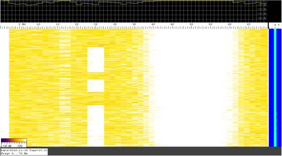
Figure
1 coaxial probe signal 0-65 Hz.
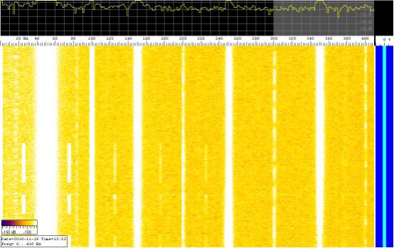
Figure 2 Coaxial probe signal 0-400 Hz.
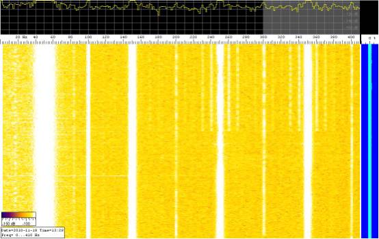
Figure 3 Coaxial probe signal 0-400 Hz with extra
signal present
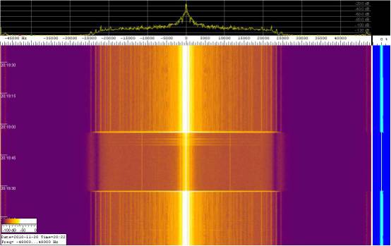
Figure 4; direct conversion receiver mode.
It can be seen that the low frequency wall voltage
dominates this spectrum. However, the wall does appear to be resolving about
five significant signals in the range 20-25 KHz and a further weak signal at
about 46-47 KHz. The presence of such
signals is closely consistent with the theoretical resonance calculation presented
above. It is interesting to note that
submarine communication frequencies dominate this frequency band. Just
lower than this frequency band power line harmonic frequencies could, also presumably, be received by the
wall, either directly or by re-radiation from space.
Experiments with the radio transceiver in receive
mode showed that the wall provided no useable antenna gain in the frequency
range 1-30 MHz over and above that provided by the connecting wire itself. Again this suggests that the lower estimates
of resonance frequency for the wall are likely to be most accurate.
An experiment was done comparing the wall voltage
function with and without mains electricity connected to the house wiring. This was facilitated using the two-pole
isolator switch located between the house electricity meter and fuse box.
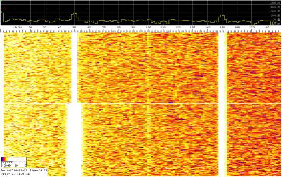
Figure 5 Mains supply on and then isolated.
It can be seen from figure 5 above that isolating
the ac mains from the house reduces the frequency spread and amplitude of the
50 Hz component. Surprisingly the low
frequency noise pick up 0-50 Hz is unaffected as are the harmonic components of
the mains frequency.
The conclusion must be somehow that the other
frequencies are coupling to the wall by a mechanism other than internal mains
current leakage. That is the wall is acting as a very low frequency antenna
with respect to mains ground. It could be it receives circulating currents
present in the outside earth wherein the foundation of the wall is seated.
Further spectra were recorded of the direct
audio spectrum from the wall. This time the signal was considerably weaker and
the Hum was not perceived directly on the PC speaker,
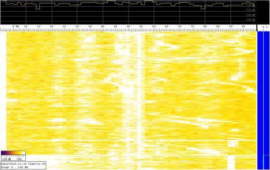
Figure 6 direct wall audio in range 0-95 Hz.
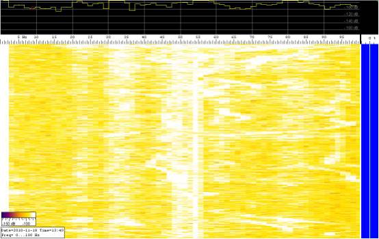
Figure 7 Direct wall audio 1 minute later.
Experiments were performed with a wider frequency
window on the spectrum analysis program but very little output was yielded even
at higher mains harmonics consistent with the wall as a low pass filter (ref).
Discussion
coaxial probe signals
The most evident feature in figures 1 and 2 is that
of 50 Hz mains component and its harmonics. This must indeed be Dawes so called
wall voltage. However, finer inspection shows other significant frequencies and
both frequency and amplitude inter-modulation products. Close inspection of the three figures shows
frequency components at 17, 25, 35 and 75 Hz in addition to mains frequencies
and harmonics. The 50 Hz band appears
very broad as though it has been modulated in frequency space from about 37-64
Hz and there is some weak evidence of time amplitude gating. Whereas the 200 and 400 Hz harmonics appear
to be strongly time gated in amplitude at the same approximately 1Hz interval
of the 17 and 35 Hz pulses. Clearly a
very complicated non-linear mixing process is at work and the sound played out
of the PC speaker took on the author’s wife’s; perception of the Hum.
Figure 3 is similar except that there appears to be
another signal process creating sidebands on the 250 and 300 Hz mains
harmonics. GSM is known to produce 217 Hz.
Discussion of wall audio output signal
The wall audio signal, figures 6 and 7 was found to
contain some similar frequency components and some dissimilar components to
those contained in the wall voltage signal. Frequency components of 23, 34, 35, 45, 50, 54, 62, 82, 85 and 95
Hz can be seen. Interestingly all the components are pulsing on and off at a
pulse repetition frequency of about 1HZ with the exception of the 54 Hz
component which is continuous although may have an upper sideband which is
pulsed. In the wall voltage signal the 17 Hz component was pulsing on and off
at about once per second as were the outer fringes of the 50 Hz components. The
higher harmonics of the mains were pulsing but at a slower rate. The similar frequency components probably
arise by direct piezoelectric conversion of the wall voltage and any received
radio signals. For the dissimilar frequency components we may well need to look
elsewhere. In this respect, it should not be forgotten that an outer cavity
wall of a house can conduct ground borne vibrations and radiate them into a
room directly as infrasound or acoustic sound.
It must be remembered that piezo-electric
conversion is a two way street.
It has been shown previously that with a mixture of
low frequency components one can perceive the Hum. (ref)
Conclusions
It is concluded that walls do indeed have ‘mouths’
and that those mouths radiate low levels of low frequency sound perhaps
dependent on the presence of external radio signals and ac mains fundamental
and harmonic frequencies. However, it must not be forgotten that an outer
cavity wall of a house can conduct ground borne vibrations and radiate them
into a room directly as infrasound or acoustic sound. The complex patterns of low-level infrasound
and sound emitted as a result of both sources are probably what some perceive
as the Hum.
The plausible hypothesis proposed by this
paper has been proven experimentally and forms a valid alternative way that
humans can perceive mainly low frequency electromagnetic energy other than by
the thermo-elastic mechanism of
microwave hearing!